Cracking the Code of Vickers Vane Pumps
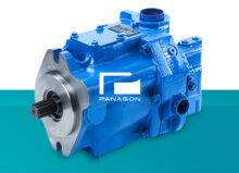
Vickers vane pumps are known for their exceptional application flexibility, long lifespan, quiet performance, and lower maintenance costs. But, they don’t last forever.
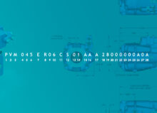
Whether it’s time for repairs or a complete replacement, knowing how to read old Vickers vane pump codes can help you save time and money. These identification codes provide a lot of information on specifications, including mounting orientation and flow rate.
Table of contents
Reading Vickers Vane Pump Identification Codes (Single Vane)
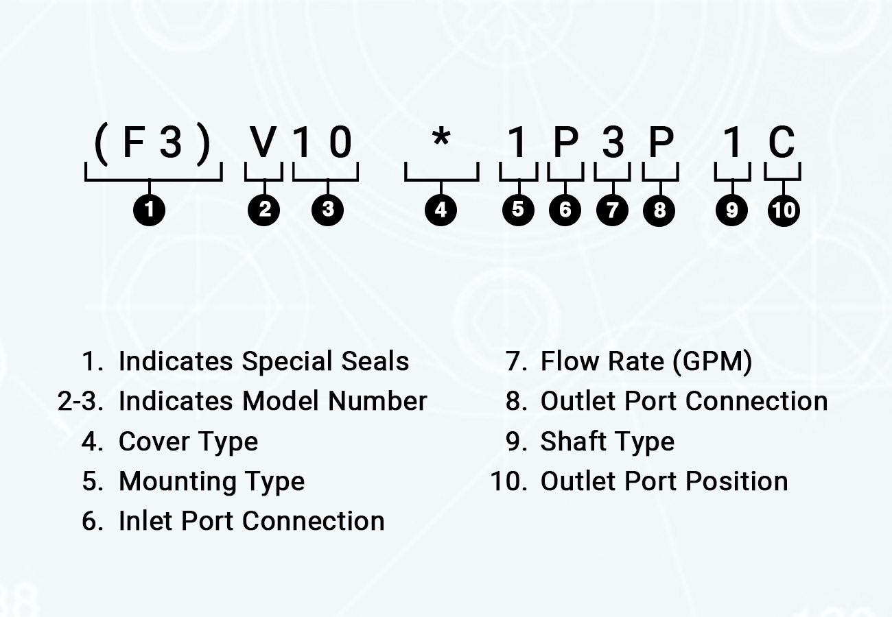
Positions 1-3: Model Code & Special Seal Indicator
With old Vickers vane pump identification codes, generally, the first position is usually a letter, and the next two are numbers. The V indicates that it’s a vane pump. The numbers in the second and third positions of the code are the model numbers.
So, if your code starts with V10 or V20, you have a V10 or V20 model pump.
The pump has special Viton seals if the identification number starts with an F3 code in the first position. If you don’t see it, that means that Viton seals are not required—in those situations, the model number should appear in the first position.
Position 4: Cover
Next, you may see an (F) or a (P) after the model number. The ‘F’ indicates the pump has a flow control cover, while the P indicates that the pump has a priority valve cover. Your pump has a standard cover if you don’t see either of these letters.
Position 5: Mounting Type
After that, the fifth number position indicates the mounting type—the most common numbers you will see are 1 and 2, which means 1- or 2-bolt flange.
Position 6: Inlet Port Connection
The sixth position is a letter indicating the inlet port connection. The four letters you would see are S, P, B, or T.
| S | P | B | T |
| 1.3125”-12 Standard Thread Connection (V10) | 1.00” NPT (V10) | 1.00” BSP (V10) | 1.1875” -12 Standard Thread (V10) |
| 1.625”-12 Standard Thread (V20) | 1.25” NPT (V20) | 1.25” BSP (V20) | Would not appear on V20 models |
Position 7: Flow Rate
The next number will vary based on whether the pump is a V10 or V20. With a V10, you would see either a 1, 2, 3, 4, 5, 6, 7. With a V20, you would see a 6, 7, 8, 9, 11, 12, or 13. This indicates GPM at 1,200 RPM. So, if you have a V20 and see a 12, it would have a 12 GPM displacement (at 1,200 RPM).
Position 8: Outlet Port Connection
The next position will be a letter indicating the type of outlet port connection it has. With the V10 and V20, you will see either an S, P, or B.
| S | P | B |
| 0.750” – 16 Standard Thread (V10) | 0.500” NPT (V10) | 0.500” BSP (V10) |
| 1.0625” – 12 Standard Thread (V20) | 0.750” NPT (V20) | 0.750” BSP (V20) |
Position 9: Shaft Type
The next number will indicate the shaft type:
- 1= Straight Keyed
- 2= Threaded (With Woodruff Key)
- 6= Woodruff Key Stub (Only on the V20 Model)
- 11= Splined
- 12= Splined (Only on the V10 Model)
- 15= Splined (Only on the V20 Model)
- 38= Splined
Position 10: Outlet Port Position
This letter indicates the outlet port position viewed from the cover end and applies to both V10 and V20 models.
- A= Opposite from the inlet
- B= 90 degrees counterclockwise from the inlet
- C= Inline with the inlet
- D= 90 degrees clockwise from the inlet
Position 11: Flow Rate Setting
This position is only applicable to models with a priority valve cover.
- (2)= 7.6 L/min
- (3)= 11.4 L/min
- (4)= 15.2 L/min
- (5)= 19.0 L/min
- (6)= 22.7 L/min
- (7)= 26.5 L/min
- (8)= 30.3 L/min
Position 12: Pressure Setting
This next position will be a letter indicating pressure setting for the flow controller. This letter will only be present in models with priority valve covers.
- A= 17 Bar/250 PSI
- B= 34 Bar/500 PSI
- C= 52 Bar/750 PSI
- D=69 Bar/1,000 PSI
- E= 86 Bar/1,250 PSI
- F= 103 Bar/1,500 PSI
- G= 121 Bar/1,750 PSI
- H= 138 Bar/2,000 PSI
- J= 155 Bar/2,250 PSI
- K=172 Bar/2,500 PSI
Position 13: Shaft Rotation
If the shaft rotation is counterclockwise, there will only be an (L) here. If it’s clockwise, there will be no letter in the thirteenth position.
Reading Vickers Vane Pump Identification Codes (Double Vane)
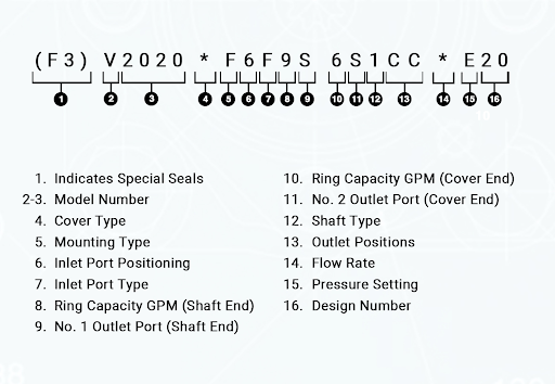
Positions 1-3: Model Code & Special Seal Indicator
Positions 1-3 will be the same as single vane pumps. If you see an F3 in the first position, this indicates that the pump requires special Viton seals. If you don’t see one, the first position will be a letter V, which indicates that it’s a vane pump. The next four numbers will indicate the model number, either 2010 or 2020.
Position 4: Cover Type
Similar to the single vane pumps, an F means it has a flow control cover, while a P means it has a priority valve cover. If there isn’t a letter here, the pump has a standard cover.
Position 5: Mounting Type
An F indicates flange-mounted, while a P indicates it’s mounted with a foot bracket.
Position 6: Inlet Port Positioning
The sixth position could be a letter or a number—you won’t see this if you have a model that’s flange mounted or if the inlet port is at 12 o’clock.
A P indicates the inlet port is at 3 o’clock (when viewed from the shaft end), a 6 indicates the inlet port is at 6 o’clock (when viewed from the shaft end), and a 9 indicates that the inlet port is at 9 o’clock (when viewed from the shaft end).
Position 7: Inlet Port Type
You may see an F here, which indicates the model has a 4-bolt flange.
Position 8: Ring Capacity (Shaft End)
You could see one of six numbers:
- 7= 7 GPM (at 1,200 RPM and 100 PSI)
- 8= 8 GPM (at 1,200 RPM and 100 PSI)
- 9= 9 GPM (at 1,200 RPM and 100 PSI)
- 11= 11 GPM (at 1,200 RPM and 100 PSI)
- 12= 12 GPM (at 1,200 RPM and 100 PSI)
- 13= 13 GPM (at 1,200 RPM and 100 PSI)
Position 9: No. 1 Outlet Port (Shaft End)
If you see an S in the ninth position, this indicates the outlet port is 1.062” 12 UN-2B thread.
Position 10: Ring Capacity (Cover End)
There are five numbers you could see in position 10, including:
- 6= 6 GPM (at 1,200 RPM and 100 PSI)
- 7= 7 GPM (at 1,200 RPM and 100 PSI)
- 8= 8 GPM (at 1,200 RPM and 100 PSI)
- 9= 9 GPM (at 1,200 RPM and 100 PSI)
- 11= 11 GPM (at 1,200 RPM and 100 PSI)
Position 11: No. 2 Outlet Port (Cover End)
There are three primary letters you could see here: P, S, or T.
| P | S | T |
| Will not appear on standard covers | 1.062”- 12 Straight Thread (Standard Cover Model) | Will not appear on standard covers |
| 0.750” – 16 Standard Thread (Pressure Flow Control Cover) | 0.750”- 16 Standard Thread (Pressure Port on Flow Control Cover Model) | 0.750” – 16 Standard Thread (Pressure Port on Flow Control Model) |
| 0.500” NPT (Tank Port on Flow Control Model) | 1.062” – 12 Standard Thread (Tank Port on Flow Control Cover Model) | 0.750” – 16 Standard Thread (Tank Port on Flow Control Model) |
| Will not appear on priority valve cover models | Will not appear on priority valve cover models | 0.750” – 16 Standard Thread for the primary outlet (Priority Valve Cover Model) 0.875” – 14 Standard Thread on the secondary outlet (Priority Valve Cover Model) 0.750” – 16 Standard Thread (Tank Port on Priority Valve Cover Model) |
Position 12: Shaft Type
There will be a 1 here, indicating a straight thread shaft type.
Position 13: Outlet Positions
The next two letters will indicate the outlet positions (from the cover end):
- A A = Opposite from the inlet
- B B= 90 degrees CCW from the inlet
- C C=Inline with the inlet
- D D= 90 degrees from the inlet
Position 14: Flow Rate
This number indicates the flow rate of the pump in GPM.
Position 15: Pressure Setting
The next position will be a letter indicating the pressure setting (in PSI):
- C= 750 PSI
- D= 1,000 PSI
- E= 1,250 PSI
- F= 1,500 PSI
- G= 1,750 PSI
- H= 2,000 PSI
- J= 2,250 PSI
- K= 2,500 PSI
Position 16: Design
The next two numbers indicate the pump design. Typically, this number is 20.
Position 17: Rotation (From Shaft End)
Similar to single vane pumps, if there is an L here, this indicates counterclockwise rotation. If there isn’t a letter at the end of the code, it has a clockwise rotation.
Other Applications
Look for a VTM and model number in the first and second positions for mobile applications. VQ indicates high-speed, high-pressure pumps after the model number.
Similar to earlier V10 and V20 models, the V series pumps are designated with the model number before the letter. On single-pump models, higher numbers generally indicate greater displacement.
The Vickers V series double pumps, from 2520V through 4535V, and the thru-drive pump series, 25VT through 45VT, are selected for use in tight spaces or when a reduction in the number of motors and drive extensions is required.
Have Questions?
Once you crack the code, the answers to Vickers pumps are easy to find. The code is the best way to understand pump specifications and what type of replacement parts are needed. If you need help finding replacement components or a replacement vane pump, please contact Panagon Systems today.