What Are the Parts of a Hydraulic Motor?
Hydraulic motors are critical components of hydraulic systems. They are mechanical actuators that convert the hydraulic pressure from the hydraulic system into mechanical energy. There are several critical parts of a hydraulic motor—these include gears, vanes, pistons, and actuators. All these parts must work together to create a hydraulic motor that works efficiently.
The parts of a hydraulic motor will vary depending on the type of hydraulic motor used in the system. Here is a breakdown of the types of hydraulic motors and their primary components.
Types of Hydraulic Motors
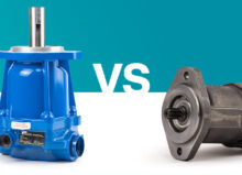
The three main types of hydraulic motors are gear, piston, and vane. Gear motors are durable, can operate at high speeds, and are typically used in rotating equipment. Vane motors are ideally suited to low-speed applications, and they’re often used in industrial equipment such as plastic injection molding machines. Piston motors are often used in heavy-duty hydraulic industrial equipment and machinery.
All three motors can be split into two primary classes: low-speed/high torque (LSHT) and high-speed/low torque (HSLT). You can visit our blog to learn more about these motors.
Below, we’ll break down each component in gear, vane, and piston pumps, their role within the motor, and how each part works together.
Gear Motor Part Breakdown
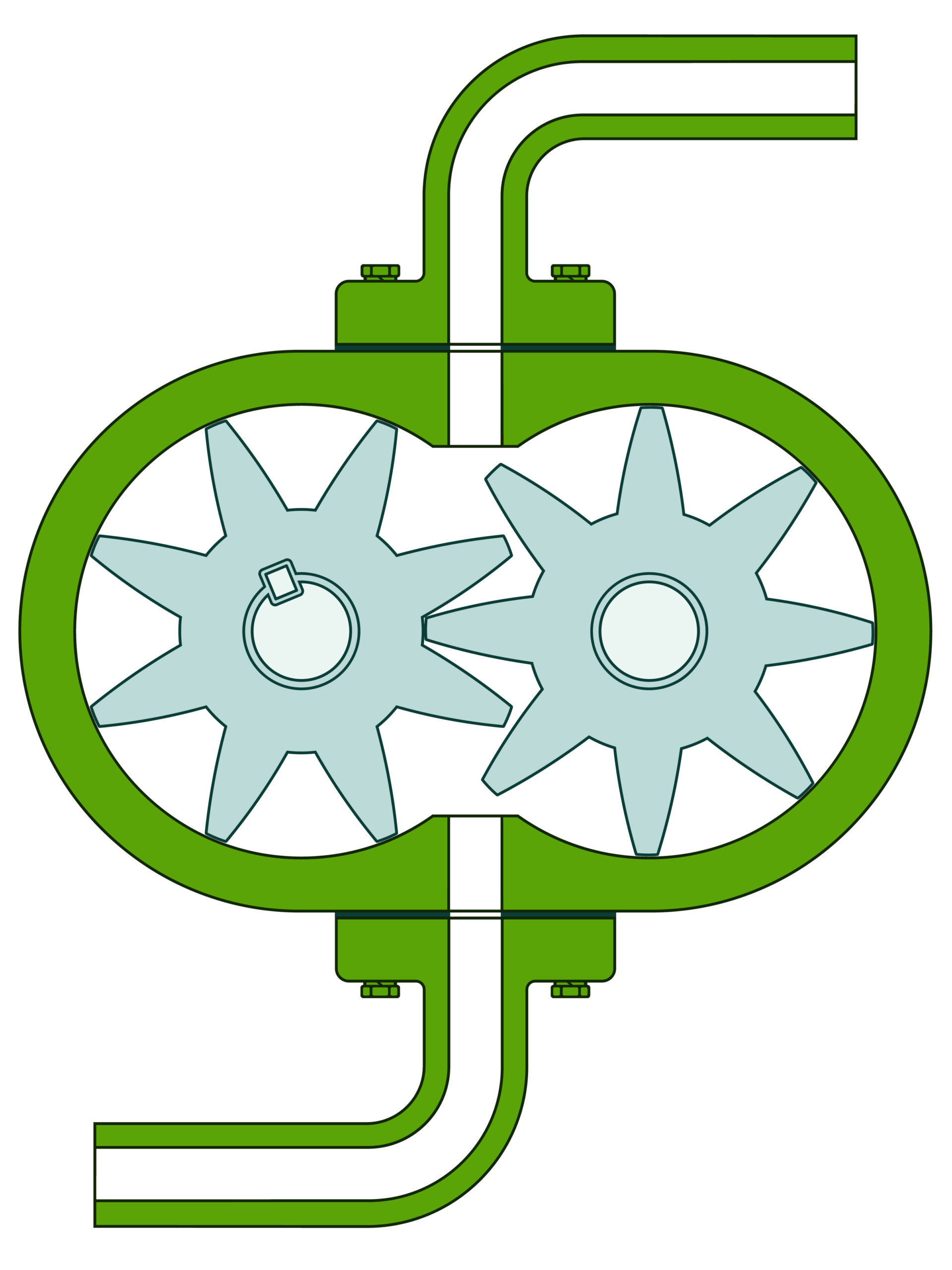
There are three main parts to a gear motor. These include the driven gear, the idler gear, and the output shaft. Fluid is forced through the inlet valve to the two interlocking gears; when these gears rotate, they generate torque. The teeth of the gears ensure that none of the fluid moving toward the outlet valve escapes back to the inlet valve.
Idler Gear
The idler gear is a stationary gear that is not attached to the output shaft. It is only used as a guide and does not operate independently. It is forced to rotate due to its teeth interlocking with the driven gear.
Driven Gear
The driven gear is attached to the output shaft and generates motion from the hydraulic fluid pressure, which is then transferred to the idler gear. The driven gear is responsible for transmitting rotational motion between the two gears.
Output Shaft
Finally, the driven gear’s motion is initiated as pressure builds. Since the driven gear is attached to the output shaft, the torque created by the driven gear is transferred through the output shaft.
Vane Motor Part Breakdown
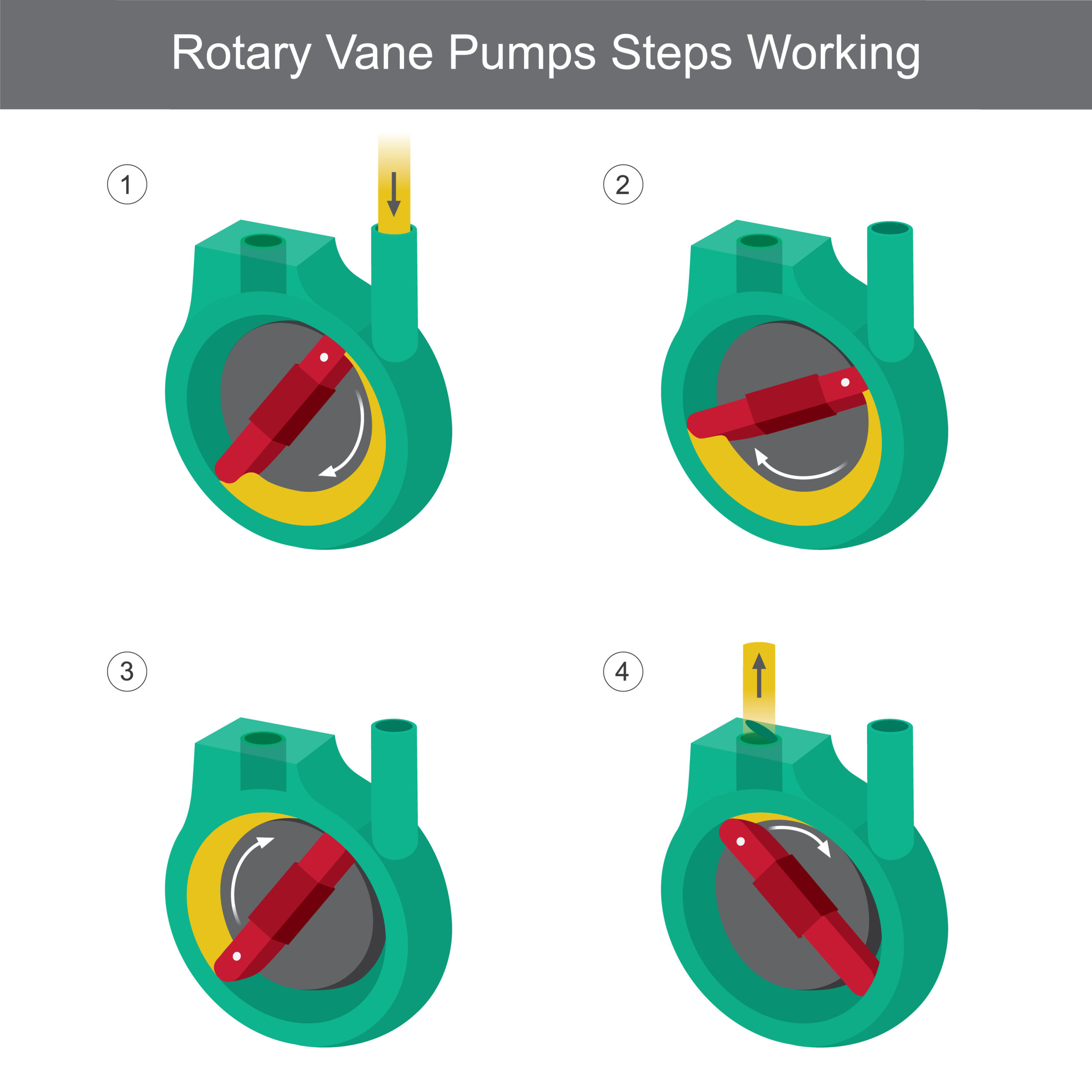
In vane motors, there is a housing (sometimes called casing) with an inlet and outlet valve. Within the housing are multiple vanes connected to a single rotor. Pressure from the hydraulic fluid is pushed through the inlet valve forcing the rotation of the rotor and the vanes, and that rotation creates torque.
Rotor
The rotor is connected to the vane motor’s drive shaft. The vanes are connected to the rotor, and the fluid pressure rotates the rotor, which in turn rotates the vanes.
Vanes
The vanes are connected to the rotor, and the length of the vanes can either be uniform or variable to maintain surface contact with the vane motor’s casing or walls. The rotation of the rotor and the vanes create the torque needed to operate a given system.
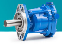
Piston Motor Part Breakdown
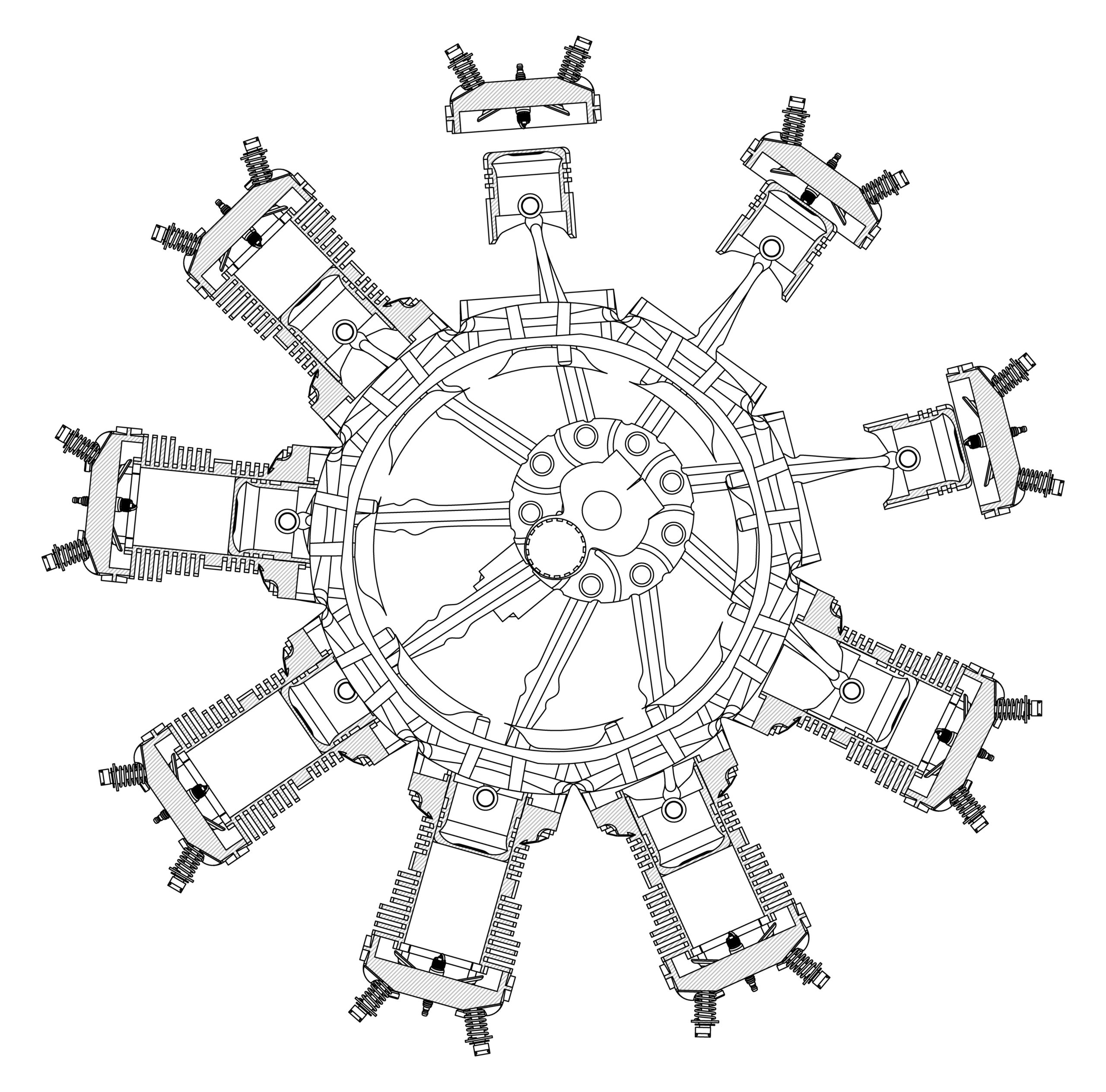
Radial engine
A piston motor has a wide displacement range that allows it to operate at high speeds. There are two primary types of piston motors: radial and axial.
Radial piston motors create torque when the hydraulic fluid pressure forces the rotation of pistons in a radial position relative to the camshaft.
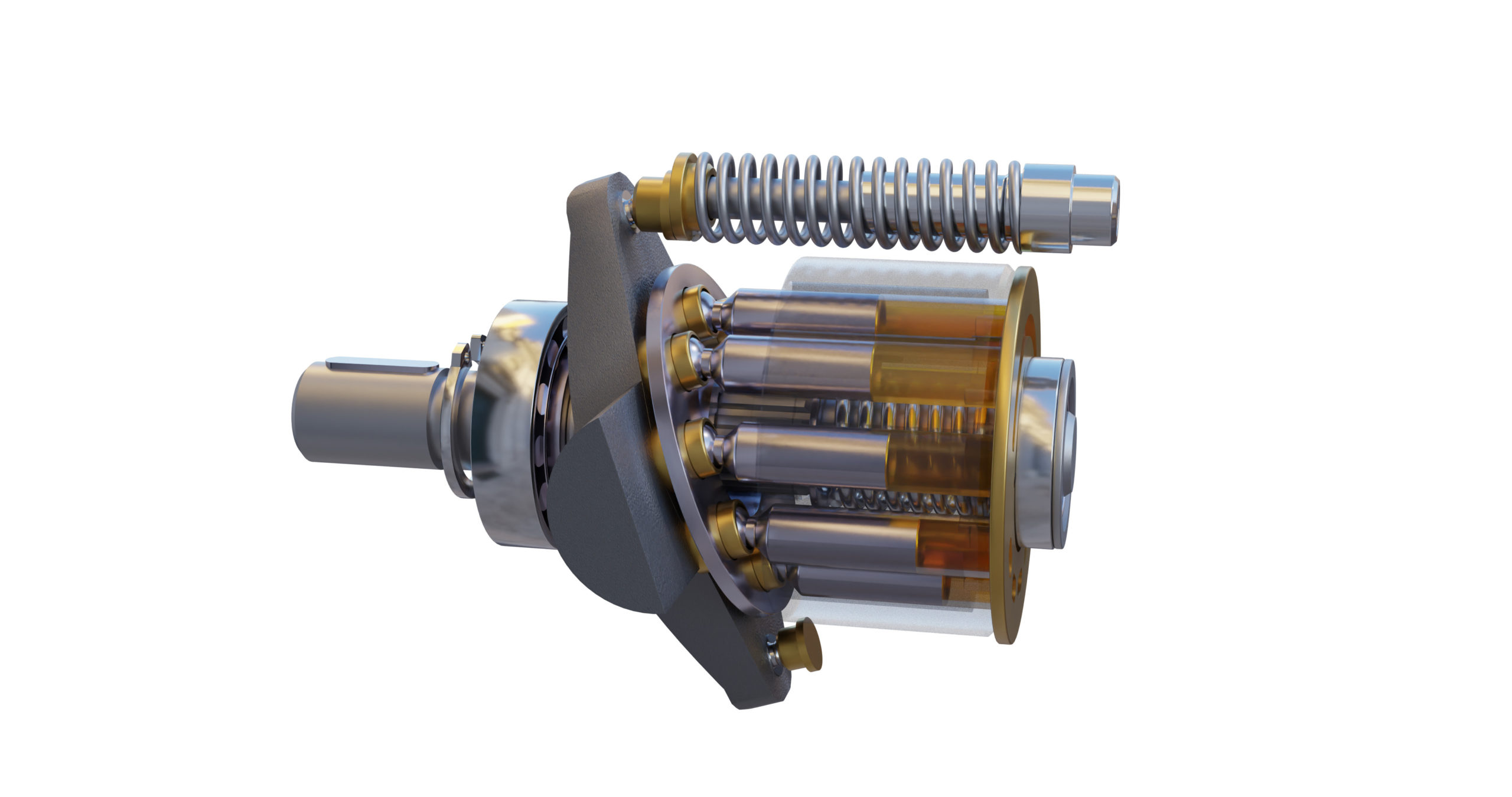
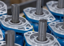
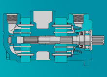
Axial piston pump
Axial piston motors are available in swashplate or bent-axis configurations.
In both configurations, the pistons and the cylinder rotate together through built-up pressure. It’s called axial because the pistons are arranged in a circular pattern along the axis of the cylinder block. Radial and axial piston motors each have an entirely different set of components.
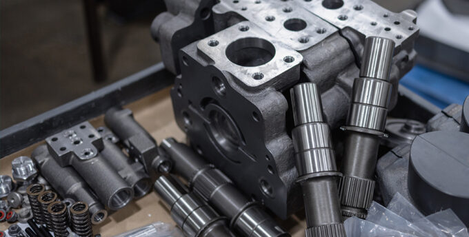
Cylinder Block
Cylinder blocks are found in axial piston motors. Its primary purpose is to house the pistons and ensure the rotation of the pistons and cylinders. When the cylinder completes a full rotation, it drives the pistons to perform a single stroke.
Rotor
Rotors are also found in axial piston motors and rotate along the cylinder block and pistons.
Stator
The stator is standard in radial piston motors. The stator provides force for the piston and rotor, ensuring that both rotate.
Pistons
Axial and radial piston motors both contain pistons. When pressure builds up in the motor, these precision-machined bars move up and down, converting energy into mechanical power.
Other Terminology You Should Know
When researching hydraulic motors, pumps, and cylinders, you may also come across the following terminology:
Bore
The bore can be viewed as the diameter of the inside of the cylinder housing the pistons. The bore’s measurement determines the piston’s size, which then determines the cylinder’s maximum pressure capacity.
Compensator
The compensator in a hydraulic motor acts as a pressure sensor. It regulates the pump flow to ensure the fluid pressure never exceeds the predetermined firing or maximum pressure setting.
Flange
A flange is a protruding mating surface typically larger than the width or the diameter of the tube or pipe it’s attached to. Flanges can have a circular, rectangle, or square mating surface. Mating two flanges together increases the strength of the two connected parts while protecting the entire system against pressure leakage, water intrusion, and vibration.
Housing
The housing protects all the motor components against contamination and damage and holds the components in their proper location. These enclosures are typically designed with high-fatigue strength material to protect against catastrophic failure.
Inlet Valve
The inlet valve is where the fluid flows in. The remaining gears and components turn that fluid pressure into mechanical power.
Outlet Valve
The outlet valve is where the fluid flows out. Most motor systems are designed so that the fluid pressure leaving the outlet valve does not escape back toward the inlet valve.
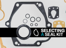
Seal
A hydraulic seal is an O-ring that is placed between mating surfaces or adjacent components. They ensure that components are protected against fluid or air pressure leakage. Different seals are often needed to seal off a given part.
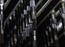
Shaft
The shaft is an elongated circular tube that rotates and transmits torque to the components it’s attached to. Each complete piston stroke causes the rotation of the shaft.
Swashplate
The swashplate acts as a converter, turning the piston’s up-and-down motion into the drive shaft’s rotational motion. The swashplate has a circular disc that is attached to the shaft.
Where to Find Replacement Hydraulic Motor Parts
Founded over 25 years ago, Panagon Systems is an industry-leading provider of replacement hydraulic motor parts and remanufacturer of hydraulic piston pumps and motors. We carry many replacement motor parts, including shoe plates, bearings, O-rings, housings/casings, cylinder blocks, and more.
Please contact us today if you have questions about hydraulic motor components or need help selecting the right replacement part.